Understanding Electricity: A Beginner's Comprehensive Guide
Written on

Understanding the Fundamentals
This tutorial is designed for both consumers and students, offering insights into volts, amps, and watts, alongside their relevance to household appliances and electrical circuits. The equations are straightforward, and examples are provided to illustrate their application to various home devices.
If you don’t have a Medium subscription, you can read this article on Dengarden here: How to Understand Electricity: Volts, Amps, Watts and Electrical Appliances
In this guide, you will explore: - Volts, watts, and amps - Power consumption of appliances along with kilowatt hours (kWh) - Ohm's law and the concept of resistance - Resistivity and its impact on material resistance - The role of fuses in protecting wiring and devices - Mechanisms of electricity generation - Tools for measuring voltage, current, and resistance - Effects of electric and magnetic fields - Types of conductors, insulators, and superconductors - Basics of alternating current (AC) and direct current (DC) - Understanding arcs and sparks - Power supplies and voltage regulation - Monitoring electricity usage in homes
What Is Electricity and Electric Current?
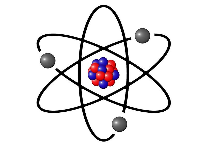
An electric current refers to the movement of electrons through a conductor. All substances consist of atoms, which are the fundamental units of matter. The Rutherford-Bohr model presents a simplified view of an atom, with a nucleus composed of protons and neutrons surrounded by orbitals containing electrons. In conductive materials, such as metals, electrons are loosely bound to the nucleus, allowing them to detach and flow when a voltage is applied. These materials are termed conductors, capable of conducting electricity. The movement of these electrons constitutes an electric current.
How Does Current Flow in a Circuit?
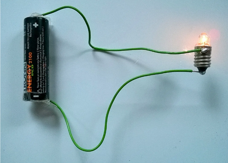
In the illustration below, an AA battery powers a flashlight bulb. Current travels from the battery's top, through the connecting wire and bulb, and returns via the bottom wire, forming a complete loop. Thus, two wires are essential to connect the voltage source to the load.
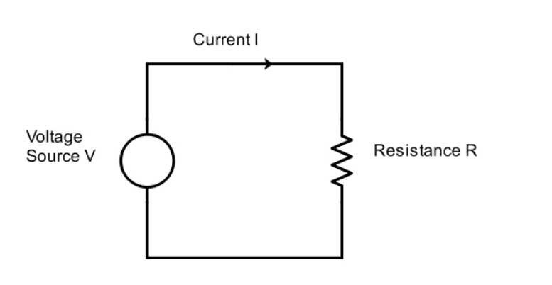
This circuit can be depicted using a schematic or circuit diagram. In the schematic below, a voltage source (V) drives a current (I) through a load (the bulb, in this example) with resistance (R). The load could be any electrical appliance, like a heater, bulb, or motor. The wires connecting the source to the load represent the conductive materials within appliances or power cables.
Ohm's Law The current (I) can be calculated using the formula:
Further details on Ohm's Law will be provided later, along with practical examples.
Current Direction in a Circuit
Traditionally, current is understood to flow out from the positive terminal of a battery. However, since current involves the flow of negatively charged electrons, it actually flows from the battery's negative terminal.
Examples of Voltage Sources
Common voltage sources include: - Batteries - Main voltage from wall outlets - Alternators or DC generators (dynamos) - Solar cells - Thermopiles - Laboratory power supplies
The Water Pipe Analogy
Voltage and current can be compared to water pressure and flow rate, respectively, with references to pumps and pipes often used to illustrate electrical concepts.
Understanding Watts, Amps, and Volts
Electrical engineering has its own terminology.
What are Volts?
Voltage signifies the pressure within a circuit and is measured in volts. Imagine a pump in a water pipe: the higher the pressure it exerts, the greater the water flow. Similarly, a voltage source acts like a pump, pushing electrons through the circuit. A higher applied voltage results in a larger current.
What Are Amps?
Electric current, caused by the movement of electrons through a conductor, is measured in amps. A high current indicates a large number of electrons flowing through the circuit, akin to a high water flow rate.
What is a Load?
This term refers to devices connected to a voltage source, such as motors, bulbs, heaters, or resistors.
What Are Watts?
Power, measured in watts, indicates the rate at which energy is consumed by a load. A kilowatt equals 1000 watts, often denoted as kW. Lower power levels are measured in milliwatts (mW).
What Are KWh or Kilowatt Hours?
KWh measures energy consumption and is sometimes referred to as units, which appear on your electricity bill. For instance, a 1 kilowatt appliance uses one kilowatt hour of electricity in one hour, while a 500-watt device uses one kilowatt hour over two hours.
Commonly Used Voltages
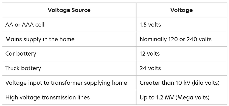
How to Convert Between Volts, Amps, and Watts
Let’s look at the quantities usually relevant when dealing with appliances, specifically volts, amps, and watts, and the conversion methods between them. Usually, you can find a specification label on an appliance's casing indicating voltage, frequency, wattage, and possibly current.
The crucial equation is:
Once you understand this, you can rearrange it to find the other two quantities.
Examples of Calculating Watts, Amps, and Volts for Appliances
How to Calculate Watts
For instance, if a 120-volt appliance draws 2 amps, what is its power?
Power in watts = 120 × 2 = 240 watts.
How to Calculate Amps
For example, if a 240-volt appliance consumes 480 watts, what is the current it draws?
Current in amps = 480 / 240 = 2 amps.
How to Calculate Volts
For instance, if a 720-watt appliance uses 3 amps, what voltage is it operating on?
Voltage in volts = 720 / 3 = 240 volts.
This process is quite straightforward. The chosen values in the examples are designed for easy calculations. Remember, you need to know two quantities to solve for the third.
For high-powered devices, power is often expressed in kilowatts (kW), where:

What Is a kWh? — Calculating Energy Consumption
Power indicates the speed at which energy is consumed by a device. For instance, an air conditioning unit or a shower uses electrical energy much faster than a light bulb.
Energy Used = Power × Time
To calculate an appliance's energy usage, multiply its power rating by the duration of its operation. Energy is typically measured in kilowatt hours (kWh), also known as units. The formula for calculating kWh is:
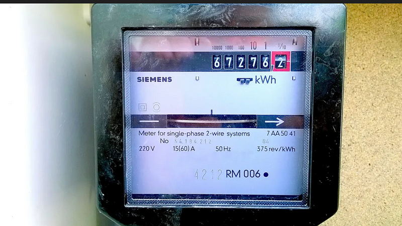
Kilowatt hours or units are what you pay for on your electricity bill. Your electricity meter counts the total units consumed by all appliances and lights in your home.
For example, if a 2500-watt dryer runs for 3 hours, how many kWh does it use, and if the cost of electricity is 12 cents per unit, what would be the total cost?
Cost = 7.5 × 12 cents = 90 cents.
Some appliances do not operate continuously. Devices controlled by a thermostat, such as refrigerators, freezers, and ovens, may only draw power intermittently. The time an appliance is powered on is referred to as its duty cycle, often expressed as a percentage. For instance, a refrigerator that runs half the time has a 50% duty cycle.
Labels on Appliances Indicating Voltage, Current, and Power Ratings
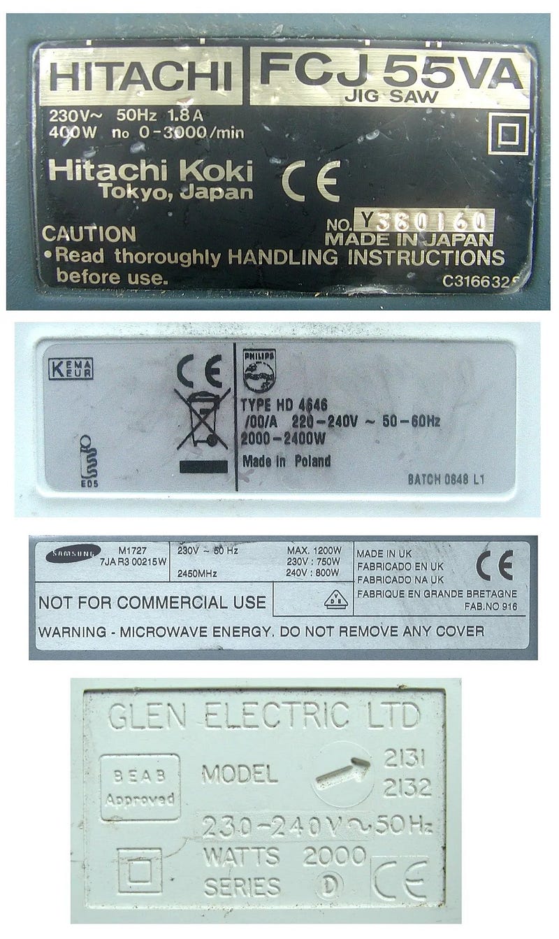
Calculating Power Consumption of Electrical Devices
For a comprehensive list of home appliances, their power consumption, and running costs, see my guide, What is the Cost of Running Electrical Appliances?
How to Convert Horsepower to Watts
Horsepower measures power, just like wattage does.
1 horsepower = 746 watts.
For instance, a fractional horsepower motor in a washing machine rated at 1/2 horsepower would yield:
Power output = 746 watts × 0.5 = 373 watts.
It's essential to note that motors aren't 100% efficient; not all electrical power converts into mechanical power, with some dissipated as heat.
Electricity Meter for Measuring Home Energy Consumption
Recommended Literature
Introductory Circuit Analysis by Robert L Boylestad covers fundamental electrical concepts and advanced topics, such as AC theory and magnetic circuits. It's well-illustrated and suitable for high school and early college students in electrical engineering.

Ohm's Law and Electrical Resistance
In the circuit illustrated above, a voltage (V) drives a current (I) through a load, which could be any electrical device. This load resists the current flow, with its resistance measured in ohms (R).
Thus, we have:
or
This relationship is known as Ohm's Law, indicating that current is directly proportional to voltage and inversely proportional to resistance. As resistance increases, current decreases, and vice versa. The resistance in ohms quantifies how a load resists current flow. In some electronic circuits, components called resistors have specific resistance values that help regulate current.
Each electrical device possesses some level of resistance. Resistance acts as a barrier to electron flow, and energy dissipates as heat in resistive materials. For a constant voltage applied to a load, greater resistance results in lower current. In the water analogy, stepping on a hose increases resistance and restricts flow. To restore flow, the pump must exert more pressure, or removing your foot from the hose increases diameter and decreases resistance.
In electrical circuits, increasing the source voltage forces more current through resistance. Even wire connections have inherent resistance, so for high currents, copper or aluminum wires must have adequate cross-sectional areas to prevent overheating.
Calculating Current Flowing Through Resistance
In a scenario where resistance is 100 ohms and a voltage of 120 volts is applied, what is the current?
Current = 120 / 100 = 1.2 amps.
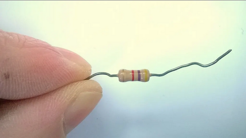
Calculating Power in a Circuit with Known Resistance and Voltage
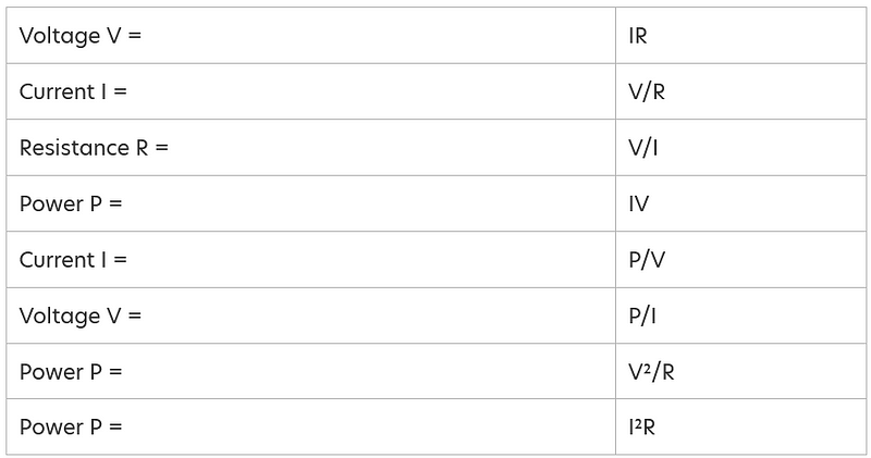
Recall that power equals volts times amps? Another method of calculating power is by using resistance in ohms:
If I represents current in amps, V is voltage, R is resistance in ohms, and P is power in watts:
From Ohm's law, we have:
Power can also be represented as:
Substituting the expression for I into the power equation gives:
Similarly:
While these last two equations might not be commonly utilized in household scenarios, here's an example:
If a 240-volt supply connects to a load of 100 ohms, what is the power consumption?
Power = V^2 / R = (240)^2 / 100 = 576 watts.
Summary of Electric Circuit Equations
What are Electrical Conductors?
A conductor is a physical medium that transmits electric current. This can include power cables, plug prongs, liquids like water, or ionized gases in discharge lamps (e.g., fluorescent lights).
In solid conductors, such as copper wire, electrical resistance correlates with the length of the conductor and inversely with its cross-sectional area. Longer wires have higher resistance, while thicker wires have lower resistance. This principle is crucial for conductors in appliances and power transmission; if an extension lead uses too thin a wire, it may overheat.
What is Resistivity and Its Impact on Resistance?
For a conductor with a cross-sectional area (A) and length (l), resistance (R) can be calculated as:
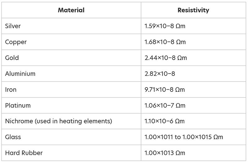
Here, ? (rho) represents a constant called resistivity, indicating a material's conductivity. Lower resistivity means lower resistance. Copper has the lowest resistivity among common materials, which is why it is widely used in wiring. Although silver has a lower resistivity than copper, its cost makes it less common. Aluminum, while having a higher resistivity than copper, is lighter and often used for overhead cables. Gold is less reactive and does not tarnish, making it a good choice for coating connectors to prevent oxidation.
What is an Insulator?
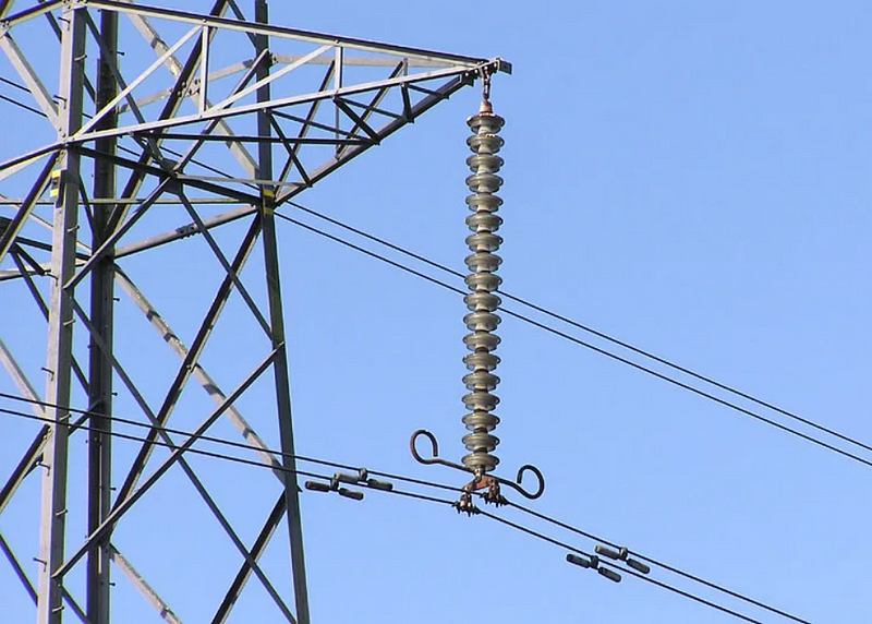
An electrical insulator is a material with extremely high resistance, preventing the flow of current due to a lack of free electrons. For practical purposes, insulators can be considered to have infinite resistance. Therefore, the current through an insulator can be expressed as:
Insulators are essential for preventing current flow between two points with different voltages, such as the insulation around power cables or plastic coverings on plugs.
Common Insulating Materials Include:
- Plastic
- Ceramic
- Glass
- Glass epoxy (for PCBs)
- Bakelite (an older thermosetting plastic)
- Mica
What is a Superconductor?
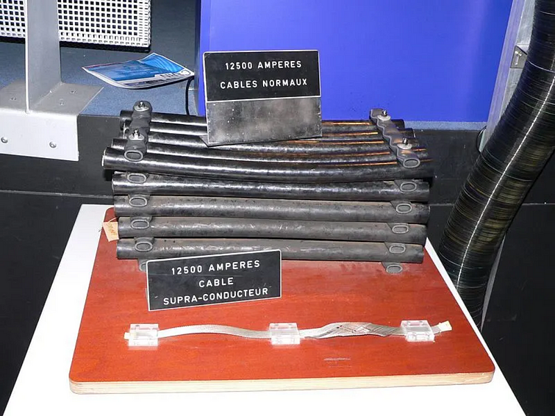
Certain materials, when cooled to very low temperatures, exhibit zero resistance. Thus, with V = IR, if R = 0, the voltage (V) becomes 0, even if current (I) exists. This means a current can continue to flow even if the voltage source is removed. Superconductors can carry substantial currents through thin cables without heat loss, which is beneficial for devices like MRI machines that require high currents for powerful magnets.
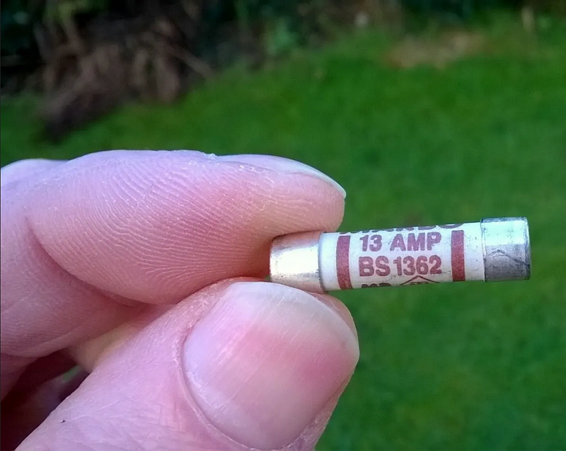
What Are Fuses For?
As previously mentioned, all electrical conductors possess resistance. This resistance generates heat when current flows. An electrical conductor may become excessively hot if too much current passes through it, potentially leading to damage or fire hazards. Fuses are employed in series with cables or appliances to restrict current flow and enhance safety. They act as a "weak link" that blows before any damage occurs. Fuses are rated based on the current they can carry without blowing. If current exceeds this rating, the fuse will blow, with the time taken to do so proportional to the current level.
Breaking Capacity of Fuses
Fuses have a maximum current threshold they can carry without damage. For domestic power supplies, glass fuses are typically used because they can handle smaller energy sources. Ceramic fuses are employed in situations where inrush currents can be substantial, as they can withstand the heat and shock of high currents. For instance, the BS1362 fuse in UK plugs is ceramic to endure high inrush currents. Always replace blown fuses with the same type to prevent fire hazards.
Types of Fuses
Fuses are generally classified as fast blow (F) or time lag (T). Time lag fuses are commonly used in electronic devices because capacitors need a surge of current during charging, which could otherwise blow a fast-acting fuse.
How Many Amps Are Supplied to Our Homes?
The answer varies by country, but for a typical 230-volt home supply in the UK, the main fuse rating is 80 amps at the consumer unit. This maximum current allows a power draw of 230 x 80 = 18.4 kW.
How Do You Check Voltage with a Multimeter?
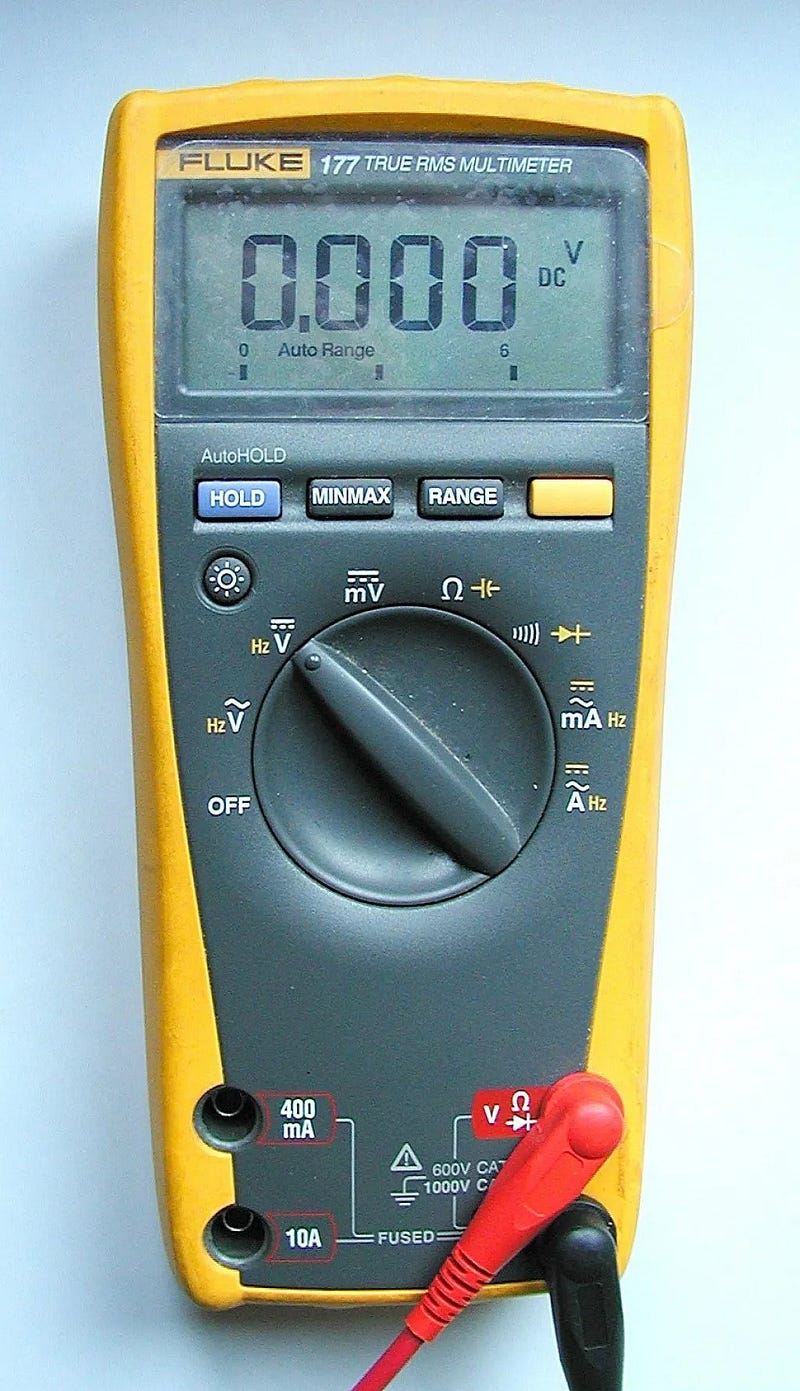
A multimeter is a device used to measure voltage, current, resistance, and other parameters. It can also test cable continuity and check fuses. For guidance on how to use one, refer to my article How to Use a Digital Multimeter (DMM) to Measure Voltage, Current, and Resistance.
Electrical Energy Consumption
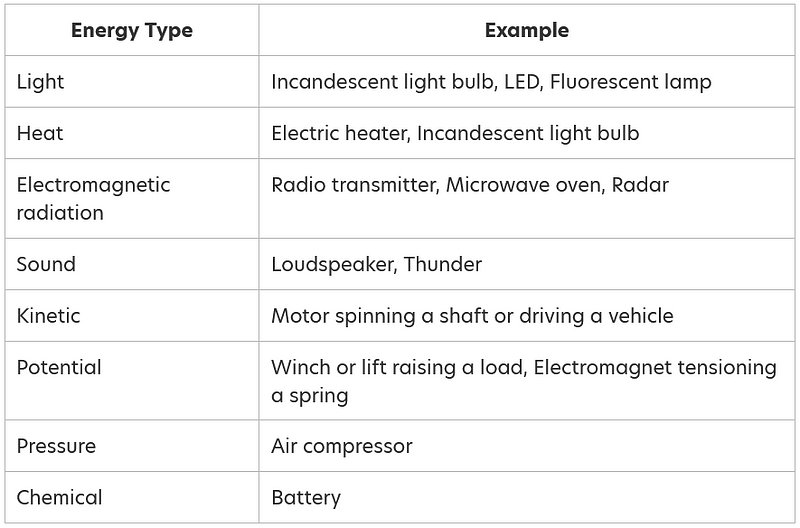
When an appliance draws power from electricity, it's important to note that energy cannot be destroyed; it merely changes forms. For instance, a rock perched on a cliff possesses potential energy, which converts to kinetic energy when it falls. Upon impact, this energy dissipates as heat. Similarly, when an appliance is plugged in, electricity transforms into various energy forms, such as light from a lamp or heat from a heater.
Power measures the rate at which energy is utilized. A 1000-watt heater or an air conditioning unit consumes energy faster than a 60-watt bulb.
How is Electricity Converted to Other Forms of Energy?
What is Three-Phase Voltage?
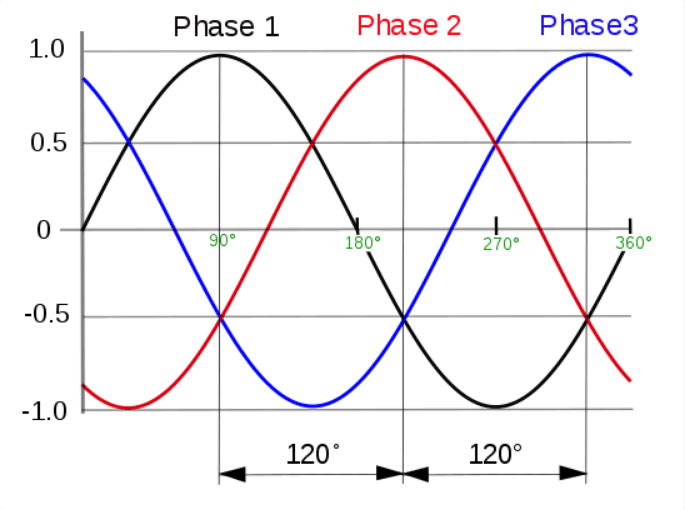
Long-distance transmission often employs DC to minimize losses; however, power is predominantly distributed through a 3-phase system. Each phase possesses a sinusoidal waveform, with a 120-degree separation. The following graph illustrates this: phase 1 is a sine wave, phase 2 lags by 120 degrees, and phase 3 lags by 240 degrees (or leads by 120 degrees). Only three wires are necessary to transmit power due to the lack of current in the neutral wire for balanced loads. The transformer supplying electricity to homes utilizes three-phase lines for input and provides three-phase lines plus a neutral output.
Why Use 3 Phase?
- Transmitting more power with fewer wires
- Smaller motors compared to single-phase motors of equivalent power
- Smoother output torque reduces motor vibration
- Smaller neutral conductor due to lower current flow
- Neutral is not necessary for power transmission between substations
Note: A “phase” represents a single winding in an alternator, transformer, motor, or resistive load. The phase voltage is the voltage across a phase.
3 Phase Formulas
If VP is the phase voltage and VL is the line voltage between phases:
Delta load:
Star load:
For balanced loads with a power factor of 1:
Delta-Star Transformer
A Delta-star transformer is commonly used to create a three-phase or single-phase supply for homes and industries, typically receiving an 11 kV input and providing a 230-volt output phase.
What Are Other Effects When a Current Flows?
When current passes through a load's resistance, it generates heat. While this effect is often desired in heaters, it can be unwanted in devices like lamps, where the primary function is to produce light rather than heat. Excessive current in power cables can lead to fires if protective devices like fuses or MCBs (Miniature Circuit Breakers) are absent.
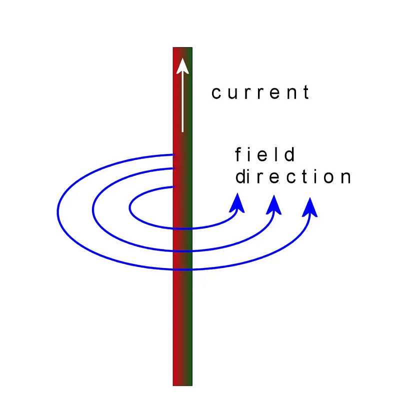
Current flow produces: - Magnetic fields: This principle is utilized in devices like solenoids or electromagnets, which are coils of wire that carry current. Electromagnets are found in various applications, such as doorbells, washing machine valves, and vehicle starter motors. - Electric fields: Current flowing through a conductor generates an electric field. A notable example is the high-intensity field under high-voltage power lines, which can illuminate a fluorescent tube held nearby.
How Do Switches Work and What Are Sparks?
As discussed, increasing resistance in a circuit reduces current flow. If a conductor is broken, creating an air gap, the resistance effectively becomes infinite, preventing current flow:
This principle underlies how switches operate. Two brass contacts in a switch connect when the switch is closed and separate to interrupt current flow when turned off.
What Are Sparks?
Consider two electrodes separated by an air gap (such as in a spark plug). If the voltage is sufficiently high, the air gap becomes ionized, allowing electrons to flow and create a spark. This spark can produce light, heat, UV radiation, and sound, reaching temperatures of around 5000 degrees Celsius, exceeding the sun's surface temperature.
Sparks can vary in size, from small ones in automotive spark plugs to larger instances like lightning, which occurs when charged clouds create high voltage differences.
Sparks are generated when voltage surpasses the breakdown voltage of the gap. When electrodes separate, the current may continue to flow, leading to a continuous discharge known as an arc. Switches must be designed to ensure that contacts separate quickly enough to extinguish arcs, especially in high-voltage applications.
Arc Between Switch Contacts at a Substation
What is a Voltage Regulator?
A voltage regulator is an electronic component that maintains the output voltage of a power supply at a constant level, regardless of the current drawn by the load. Typically implemented as single ICs or modules, a regulator that decreases voltage is termed a buck regulator, while one that increases voltage is called a boost regulator.
Unregulated voltage supplies experience output drops as current increases due to internal resistance, which creates a voltage drop while current flows, leading to a lower output than the open circuit voltage without a load.
What Are Voltage Regulators Used For?
- Stabilizing voltage for consistent electronic circuitry performance
- Vehicle alternators include voltage regulators to maintain constant charging voltage to the battery
Types of Voltage Regulators
There are two main types of regulators: linear regulators and switching regulators.
Linear Regulator: This semiconductor device functions as a controlled dropper resistor between the input supply and the output. It monitors output voltage, adjusting resistance as the load changes to maintain a constant output.
Disadvantages of Linear Regulators
Since linear regulators operate in series with the load, the input current matches the load's current. However, power loss as heat occurs due to the voltage drop across the regulator. Higher input voltages result in greater energy waste, necessitating heat sinks based on ambient temperature and voltage drop.
Switching Regulators: These regulators operate differently and can achieve efficiencies up to 95%. In buck mode (for voltage reduction), they chop the input voltage into a pulsed waveform, smoothing it with a capacitor/inductor to maintain a constant output voltage.
What Is an Electricity Usage Monitor?
An electricity usage monitor or tracker provides comprehensive information about appliance performance. Displayed on an LCD screen, parameters include voltage, current, power consumption, kWh used, operational costs, and runtime. This data is particularly useful for diagnosing issues with appliances controlled by thermostats.
References
Boylestad, Robert L. (1968). Introductory Circuit Analysis (6th ed. 1990). Merrill Publishing Company, London, England.
Disclaimer
This content is accurate and true to the best of the author’s knowledge and is not meant to substitute for formal and individualized advice from a qualified professional.
Sign up for a Medium membership here (I will receive a portion of your membership fee)
This article was first published on Hubpages.com on 19th January, 2012